X5-CD Product Manual
Setup Instructions
1. Unpack – Remove all components from packaging.
2. Handle Installation – Remove Handles from bag, unscrew mounting hardware from sides of feeder, reinstall with Handles in place and tighten. (see illustration below 3)
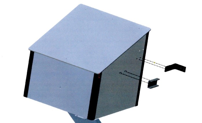
3. Hanger Bracket Installation – Remove Hanger Brackets from bag, unscrew mounting hardware from side of feeder, reinstall with Hanger Brackets in place and tighten. Use the lower set of mounting holes, move to upper only if final chute position is not favorable.
4. Feeder Mounting – Determine where feeder will be used. If on fence or any type of tubular style structure you will be using the (2) hose clamps. If on a wall type structure the (4) Mounting Screws will be used.
Note – Due to so many potential applications the mounting may need to be improvised. If you are having trouble, feel free to contact the factory for advice or even special mounting hardware.
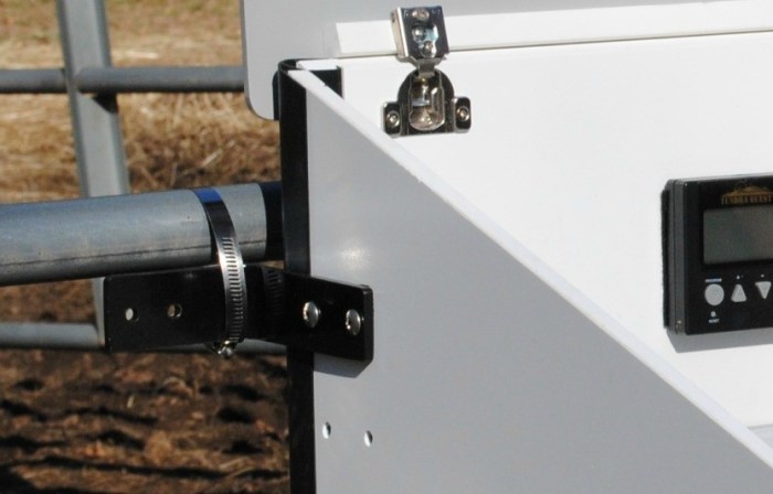
5. Fence Mounting – When mounting to any tubular style fencing or containment the Hose Clamp method is ideal. (see photo) Simply open hose clamp fully, wrap around fence tube in approximate location of where feeder is to reside and screw clamp partially closed. This should leave the clamp free to be moved along the mounting tube. Repeat this with second clamp. With some help from an assistant lift feeder into position, align with tube and slide clamps over mounting brackets. Move unit to desired place and tighten clamps until unit is secured.
6. Wall Mounting – When mounting to any wooden surface the unit will be screwed on. This will require a drill. The screws supplied are self tapping and do not require a pre-drilled hole, but if you are using a hand screwdriver it is recommended to pre-drill the holes (drill bit provided) to help in the mounting process.
(a) Find a suitable location for the unit. With the help from an assistant hold unit in the proper location and mark the (4) mounting holes. Remove feeder. Using the supplied drill bit, drill all the marked spots approx. 1”deep. Secure unit using all (4) mounting screws. See the following illustration for mounting height recommendations.
Mounting Height Recommendations
Mounting Height
Minimum mounting height is 24” from the bottom of the unit to the ground.

Wall Opening Dimensions
The 6” x 12” Chute Opening is referenced from the bottom of the feeder.

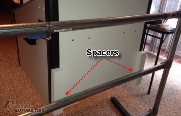
7. Squaring the Unit – The unit will need to be squared up to its mounting surface. This is achieved by adding spacers between the Back Wall and the Fence or Mounting Wall. Shims can be combined to reach the correct thickness, once correct stack is made remove tape liner and adhere Shims to backside of unit. (see photo)
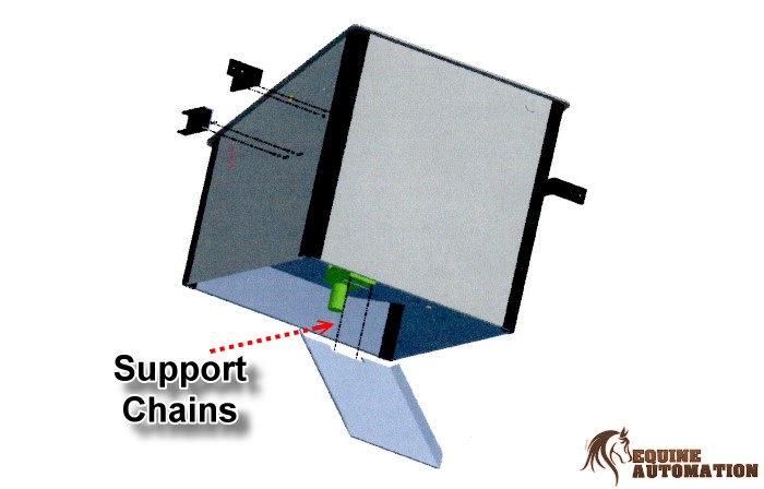
8. Chute Installation – Remove Chute from bag. Remove the (2) mounting screws from the Gearbox located on the underside of the Feeder. Align the Chute over the Beaded Support Chain and through any opening in wall or fence. Reuse the screws to secure the Chute. Note-the screws will bottom out short of the Chute being fully secured. This is intentional and by design. If the chute does not rest on a wall face or a fence section the Beaded Support Chain must be adjusted to support the chute. (see illustration)
9. Connect Drive Motor – For storage and shipping purposes the final Drive Motor has been disconnect. At this time simply plug the pair of three wire connectors, located on the underside of the unit, into each other. There is only one way they can be connected. Your unit is ready to be programmed.
Programming Timer (9/2023 to current)
 Clock Program:
Press right arrow on home screen to enter clock program. Press left arrow when finished.
- Adjust hour with up and down arrow. Press right arrow when complete.
- Adjust minute with up and down arrow. Press right arrow when complete.
- Adjust day with up and down arrow. Press right arrow when complete.
Operation Program:
On main screen, use up and down arrows to change operation mode between QSET1 / QSET2 / Custom.
ALL PROGRAMMING AND OPERATION WILL TAKE PLACE IN CUSTOM MODE. THE FEEDER WILL NOT EXECUTE FEED CYCLES IN QSET1 OR QSET2. THESE OPTIONS ARE NOT TO BE USED.
When in custom mode, press LEFT arrow to enter Timer Programming.
Press Left arrow again to see time slots.
Use UP and DOWN arrows to select time slots.
To make changes to program push Right arrow. (a flashing screen will indicate changes can be performed)
Continue pushing RIGHT arrow to see all configurable settings. When ready to make changes use UP and DOWN arrows. Settings include; Days of the week, Time of day and Duration MUST BE SET AT 2 SECONDS.
To SAVE just let unit time out or push LEFT arrow.
Tip – try to get familiar with the sequence so you can navigate swiftly without being “kicked out” repeatedly.
Test Mode:
To test feeder, press and hold right arrow until 5 second countdown begins. When countdown finishes feeder will rotate one complete cycle.
Programming Timer (1/2022 to 8/2023 Models)
Clock Program:
Press right arrow on home screen to enter clock program. Press left arrow when finished.
- Adjust hour with up and down arrow. Press right arrow when complete.
- Adjust minute with up and down arrow. Press right arrow when complete.
- Adjust day with up and down arrow. Press right arrow when complete.
Operation Program:
On main screen, use up and down arrows to change operation mode between QSET1 / QSET2 / Custom.
ALL PROGRAMMING AND OPERATION WILL TAKE PLACE IN CUSTOM MODE. THE FEEDER WILL NOT EXECUTE FEED CYCLES IN QSET1 OR QSET2. THESE OPTIONS ARE NOT TO BE USED.
When in custom mode, press LEFT arrow to enter Timer Programming.
Press Left arrow again to see time slots.
Use UP and DOWN arrows to select time slots.
To make changes to program push Right arrow. (a flashing screen will indicate changes can be performed)
Continue pushing RIGHT arrow to see all configurable settings. When ready to make changes use UP and DOWN arrows. Settings include; Days of the week, Time of day and Duration MUST BE SET AT 15 SECONDS.
To SAVE just let unit time out or push LEFT arrow.
Tip – try to get familiar with the sequence so you can navigate swiftly without being “kicked out” repeatedly.
Test Mode:
To test feeder, press and hold right arrow until 5 second countdown begins. When countdown finishes feeder will rotate one complete cycle.
Programming Timer (Pre 2021 Version)
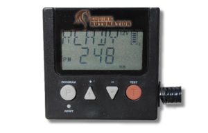
1. Clock Setup – If screen is blank press + button to activate. Press the ▲ button or P button once from the “READY” mode to enter the “CLOCK” mode. Press the P button again to enter clock settings. Use the + or – buttons to adjust to the desired weekday, then press P button and use the + or – buttons to adjust hour, then press P button and use the + or – buttons to adjust minutes. After the time is set wait 10 seconds to go back to “READY” mode automatically.
2. Setting the Feed time, Run time, & RPM
- If screen is blank press + or – button to activate screen
- Press + button once to see “CLOCK” screen
- Press + button again to see “FEED 1” screen. Continue pressing the + button to scroll through all the FEEDS 1 through 8.
NOTE – Feed cycles 6, 7 & 8 are not used and must be turned off - When reaching the desired screen press P button to begin programming.
- Repeatedly press P button to scroll through settings. The screen sequence will be:
• Day/Week setting (any one day, week or weekend)
• Hour setting (1-12, AM or PM)
• Minute setting (1-59)
• Duration setting (factory set to 7 seconds)
• RPM setting (factory set to “HI”)
The flashing feature on the screen will change with each press of the “P” button. Only when a feature is flashing can it be changed. To change that feature use the + or – buttons to make changes. When satisfied, press P button to move on to next setting. When finished press P button until no flashing features appear. Now use the + button to scroll to next FEED CYCLE. - Repeat “Item e” until Feeds 1 – 5 have been completed.
3. Programming Tips
- Write out your schedule on paper prior to programming. Timer will default out of programming mode if idle for more then 10 seconds and you will be forced to restart.
- Only use “Feed Cycles 1 through 5”. Timer has capacity for up to 8. Cycles 6-8 should not be used, reading “OFF” at all times.
- RPM/MOTOR SPEED need not be adjusted; factory setting is “HI” and is shipped this way. If changed for any reasons make necessary adjustments
- DURATION need not be adjusted. Factory setting is 7 seconds. If changed for any reasons make necessary adjustments.
- Extreme cold weather may cause the LCD (Liquid Crystal Display) screen to react slowly until the temperature warms up. Despite the lazy display of the LCD, the digital timer is working properly and will go off as per the program.
4. Testing Unit – To test the unit, press and release the “TEST” button. The unit will turn on after a 10 second delay. The unit will index one feed position and stop.
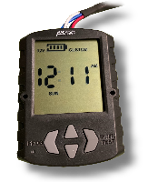
5. Check Battery Charge – If screen is blank press the + button to activate display. In the upper right corner of the screen is the 5-baricon meter. Normal operating range is 4-5 bars, recharge recommended at 2-3 bars, unreliable operation at 0-1 bars.
Recharging Battery
1. The 5-baricon meter (located in the upper right corner of display screen) displays the current health of the battery. Typical battery life is 3-5 weeks. It is recommended to recharge the unit once a month or more frequently if needed. Set up a monthly reminder in your phone. Variables affecting charge life are; extreme heat, extreme cold and age of battery.
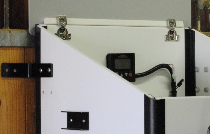
2. Your feeder comes with a charger. The charger plugs into any standard 110 volt house outlet. The other connector on the charger plugs into the recharge port located inside the feeder several inches from the controller, in the wiring harness. (see photo)
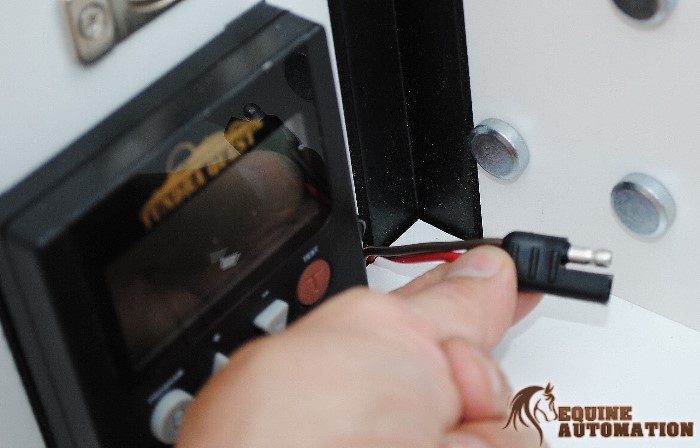
3. To Charge plug two wire plug into charge port. Plug other end onto wall outlet.
4. Normal charge time is 6-8 hours. Unit cannot be overcharged, and will operate normally while being charged. The 5-bar icon meter should read 4-5 bars when fully charged.
NOTE – It is not recommended to leave charger on for more then 24 hours.
Option – Equine Automation, LLC offers a Solar Panel (for an additional fee) which would eliminate the need to ever recharge. This is an ideal solution if a 110 volt power source is difficult to attain. The Solar Panel has a separate operation in setup manual.
Maintenance
The Equine Automation Automatic Programmable Horse Feeder is a very low maintenance unit.
From a performance standpoint there is no mandatory maintenance.
Individual preference will dictate how often you choose to clean up the interior of the unit. The Feeder is designed with a lift out Distribution Drum.


With the Drum removed a sweep and wipe down cleaning can be performed to the cabinet interior. A wash down of the Cabinet interior is not recommended.
The Distribution Drum on the other hand can be cleaned and washed down with a garden hose.
When replacing Distribution Drum, first line up onto center hub and slide on. Then gently rotate Drum until a drop and engagement is felt. Gently push Drum down to fully seat.
Warranty
Equine Automation, LLC will repair all material and workmanship defects free of charge for (1) year after the date of purchase. Battery is considered a wear item and has a (1) year replacement warranty.
The warranty does not cover damage, losses, or injury caused by unauthorized repairs, alterations, improper connection, shipping, abuse, theft, neglect or collateral loss.
In most cases a repair can be handled without returning the unit to the factory. The Feeder is designed to be modular, meaning that with basic hand tools, most repairs can be field serviceable. Only shipping expenses related to warranty issues are cover by Equine Automation, LLC.
Please contact Equine Automation, LLC for authorization prior to shipping any components.
